Overview of Components
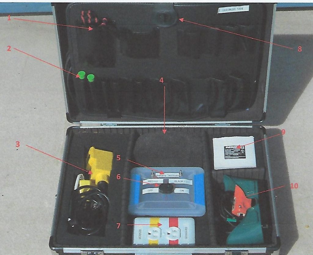
- Adjustable Shoulder Strap for Case
- 1 each Phillips Head Screwdriver and 1 each Flathead Screwdriver
- Motion Sensor and Tripod
- 12 V Rechargeable Battery (under cover)
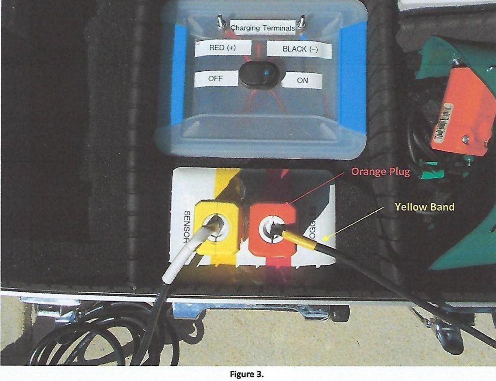
- Charging Terminals
- LED Light On/Off Switch
- Outlets for Motion Sensor and Auto Darkening Goggles
- Extension Cord (Stored behind Flap)
- Charger for 12 V Rechargeable Battery
- Auto Darkening Goggles
Assembly of Pitch Recognition Unit
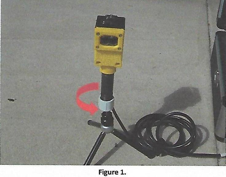
Step 1 – Screw Tripod onto bottom of Motion Sensor (Figure 1).
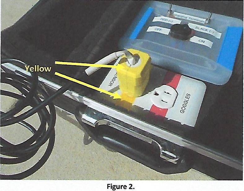
Step 2 – Insert Motion Sensor Plug into Corresponding Outlet (Figure 2).
Step 3 – Remove extension cord from Back Flap and unravel. Insert Orange Male Plug with Yellow Band into corresponding Outlet (Figure 3).
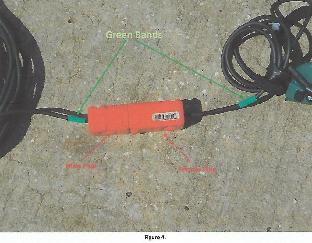
Step 4 – Insert Orange Male Plug (with Green Band) into Orange Female Plug (with Green Band) of Auto Darkening Goggles (figure 4).
Step 5 – Turn on Power
To disassemble, simply reverse order of steps.
Adjusting the Delay Feature
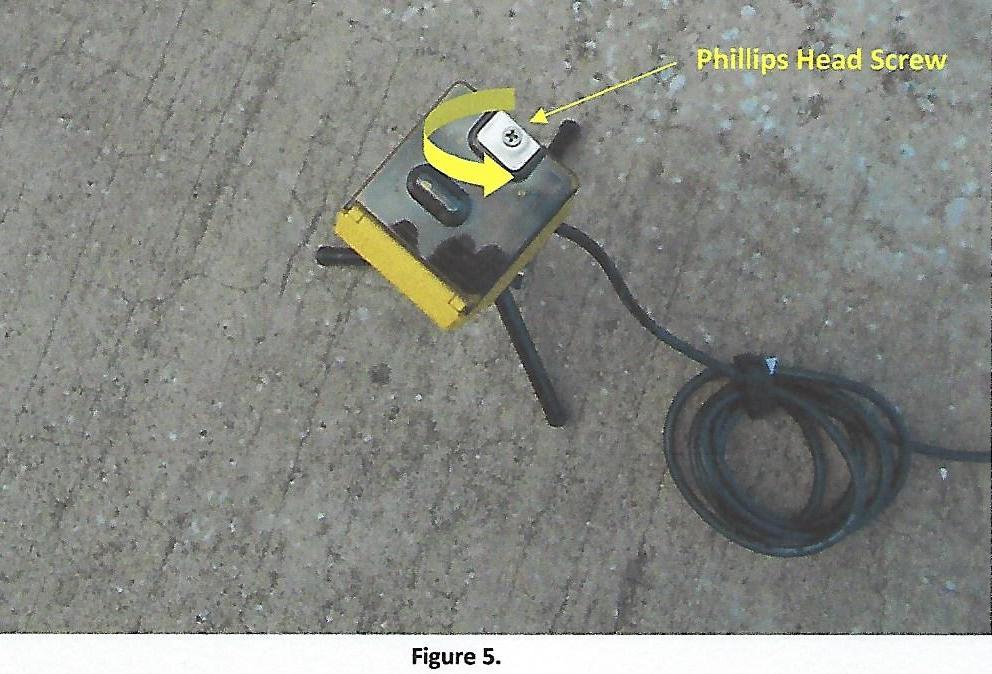
Step 1 – Using the included Phillips Head Screwdriver, loosen screw on top plate of Motion Sensor (Figure 5).
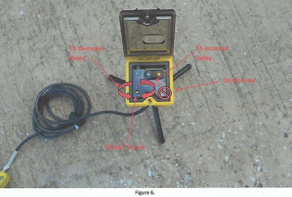
Step 2 – Using included Flathead Screwdriver, adjust the screw labelled “Delay” (Figure 6).
NOTE: Turning Clockwise increases the delay (ie hitter sees more of the pitch). Conversely, turning Counter Clockwise decreases the delay (ie hitter will see less of pitch)